I do started last year using FREECAD to learn CAD-Development and it is so far okish. I do continued to use it again and again and my skills improving. However so far i do did only geometric driven design and never something more organic like the Aeroshuttle.
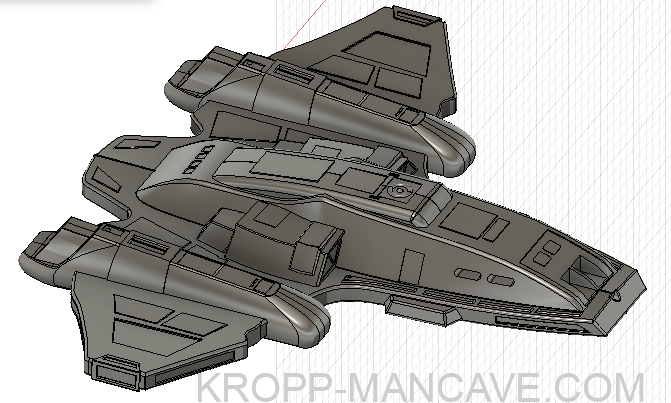
What is the Aeroshuttle?
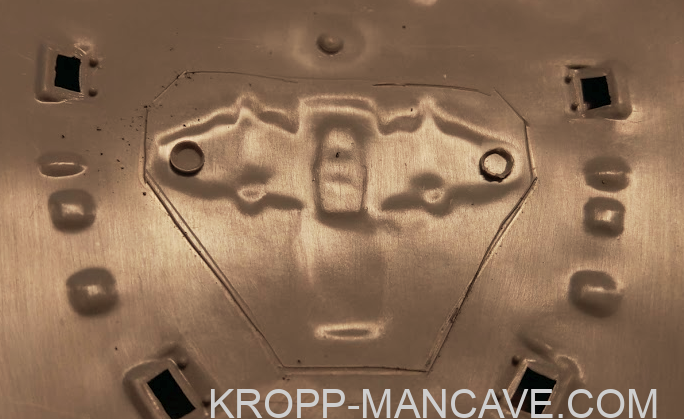
You don’t know it? Well, thats fine and no reason to be worried because it was never shown in the show. 🙂 On the downside of the Voyager Primary Hull is a small ship. IT is called the “Captains Yacht” or also known as “Aeroshuttle”. It can undock from the downer side and the Captain can normally fly away, around or whatever fun the Boss wanna do. So far Canon is the downer Side,there is also a test shot made who can be found on the internet. See below.
Useless to say that it needs to be detachable for the ultimate Voyager.
Federationmodels has a shuttle for the Revell 670 Voyager in almost the exact Style but the problem is that i can not open it to add leds into it. So I decided against it and developed my own one. As Starting Point i was using Blue Prints from the Internet as well as a Eaglemoss Model i got loaned by Mr Martens – a Model Kit builder from the greater Hamburg area.
Thanks Michael!
Organic Design – Hell! Thats a bit more Compexe as Geometric stuff…
nevertheless i have done it. I build the Aeroshuttle.
I do decided for myself that i do build it in a much bigger- larger scale as required to have the possibility to Re-Scale it as much as possible.
The actual 3d-model has a length of 85cm and i do scaled it down to something like 3.9cm. 🙂
I am playing with it at the moment, when I-am writing this Text, to find the perfect size.

After having an accurate scale in regards to length-wide-height the issue is that the Print on the Revell 670 Kit does not seems to be accurate.
if the model is matching in length direction , it finally means it is to small in the wide. The same vice versa in the same style if i do ensure an accurate print in wide.
nevertheless i do figured out that simply cutting out the footprint on the voyager and add the shuttle with some small adjustments into it will never work. I do decided that i do have to be a more accurate and professional Engineering approach.
After the Night – i started to work on it again.
Fact is we do know the size of the Shuttle. Fact is we do know the position. Fact is it will never match. for that reason i do started to offer multiple variations for any future Kit iam building or may someone else wanna build.
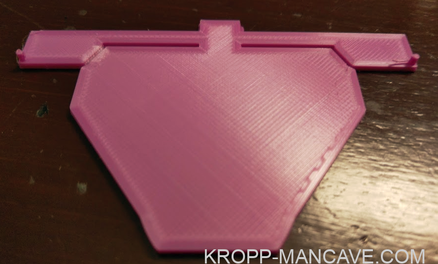
I do developed a JIG for precise positioning. IT do has two pins which you add into the available windows on the saucer. IF the front of the Saucer is looking on your direction, please pull it a little bit to you as much as possible and et’ voila – you have the perfect position. Now you need to push it down and use a cutter knife or other tools to scratch around the Jig.
On the inner side of your scratch you need to cut it out. Never do it outside of your scratch as this will simply cause a bigger whole who is not required.


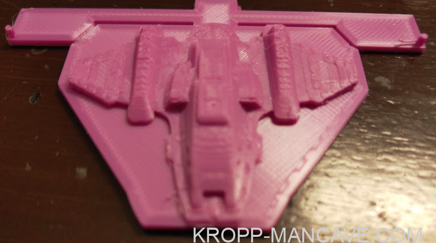

I do build the next template – thats not for final usage – but more for myself to define the best concave outer hull. I seriously wanna avoid doing a lot of Putty work to fill the concave layer.
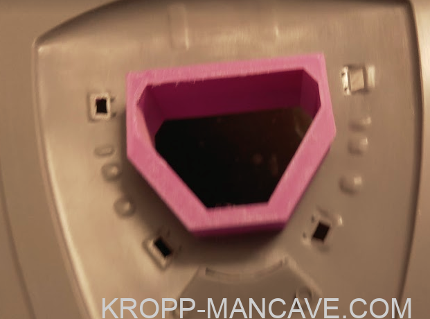
The Aeroshuttle hangar (without the hole) is matching perfectly.

2021-April-08

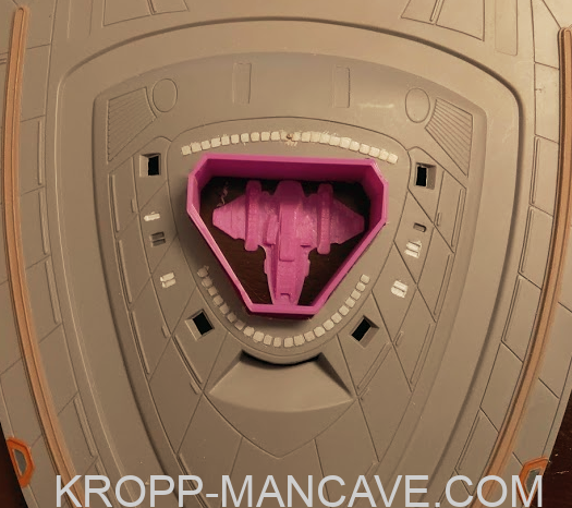
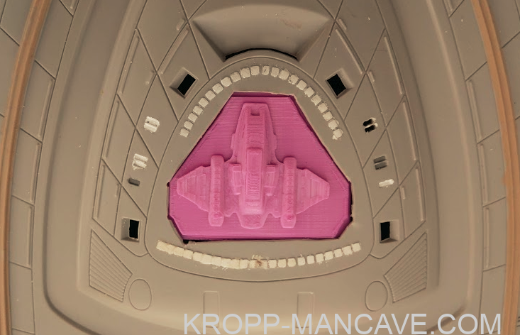
I do made some more modifications over the last few days and it is 5 Printouts later now..
the ship is perfectly matching the hole but the “hole” needs to be a bit of a half of a milimeter bigger.
Nevertheless the easy part of the Aeroshuttle-bay seems to be final.
Next step is to develop a servo controlled “fly away” of the shuttle who is leaving the ship as well as a transparent lightening cap where the LEDs are added above for indirect shiny light.
to be continued..
You want to read more? check here
Lightening the Model – in Progress
Warp Core – rejection mechanism
Shuttle Hangar – in progress
U.S.S. Voyager – Building the ULTIMATE 670 -Model
AEROSHUTTLE – Design – in Progress
Hits: 4